For high-frequency application of MESFETs, an important figure of merit is the cutoff
frequency
 , which is the frequency at which the MESFET can no longer amplify the
input signal. The small-signal input current
, which is the frequency at which the MESFET can no longer amplify the
input signal. The small-signal input current
 is the product of the
gate admittance and the small-signal gate voltage
, assuming that
the device has negligibly small series resistance
is the product of the
gate admittance and the small-signal gate voltage
, assuming that
the device has negligibly small series resistance
 |
(C.12) |
where
 is the gate capacitance equals to
 and
and
 is the average depletion-layer width under the gate electrode, and
 is the small-signal gate voltage. From the definition of the transconductance [37]
 |
(C.13) |
the output current becomes
 |
(C.14) |
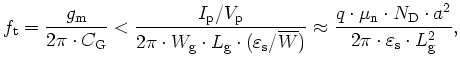
From (C.12) and (C.14) where
 , becomes
 |
(C.15) |
From (C.15) one can see that to improve high-frequency performance, a MESFET
with high carrier mobility and short channel length should be used. This is the reason that
n-channel SiC MESFET, which has a higher electron mobility, is preferred.
The
derivation in (C.15) is based on the assumption that the carrier mobility in
the channel is a constant, independent of the electric field. However, for very high-frequency
operations, the longitudinal field, i.e., the electric field direct from the source to the
drain, is sufficiently high that the carriers travel at their saturation velocity.
 |
(C.16) |
The transconductance is then
 |
(C.17) |
The value of
 is obtained from (C.5).
Finally, from (C.17), we can obtain the cutoff frequency under saturation velocity condition:
is obtained from (C.5).
Finally, from (C.17), we can obtain the cutoff frequency under saturation velocity condition:
 |
(C.18) |
Therefore, to increase
, we must reduce the gate length
 and
employ a semiconductor with a high velocity. SiC is superior to other semiconductor materials
to operate at higher cutoff frequency due to its higher electron drift velocity.
and
employ a semiconductor with a high velocity. SiC is superior to other semiconductor materials
to operate at higher cutoff frequency due to its higher electron drift velocity.
T. Ayalew: SiC Semiconductor Devices Technology, Modeling, and Simulation