
 |
|
||||
BiographyTomáš was born in Opava, Czech Republic, in 1992. He received his Bachelor degree in Mechatronics from Brno University of Technology in 2015. After an exchange year at the Norwegian University of Science and Technology, Norway, he enrolled in a Master program therein, receiving his Master's degree (MSc) in Physics in November 2018. In addition to his expertise in condensed-matter physics, Tomáš has previous experience working in the fields of numerical acoustics and robotics. Tomáš joined the Institute for Microelectronics am in July 2020, where he is working towards his doctoral degree in micromagnetic simulations for non-volatile magnetic memory devices. |
|||||
Temperature Modeling in Novel MRAM Devices and Its Effects on Switching Characteristics
Magnetoresistive Random Access Memory (MRAM) stands out as a leading non-volatile memory technology, utilizing magnetic orientation for data storage rather than electrical charge. This inherent feature grants MRAM several advantages over conventional RAM, including high endurance, high-speed operations, robustness against data loss, and low power consumption. In commercially available two-terminal (2T) Spin-Transfer Torque MRAM (STT-MRAM), spin-polarized currents passing through the memory layer stack flip the magnetic orientation of the free magnetic layer (FL) within the magnetic tunnel junction. However, due to the character of the torques, a prolonged initial incubation time (~10 ns) is present, leading to slower writing speeds and increased power consumption. Conversely, three-terminal (3T) Spin-Orbit Torque MRAM (SOT-MRAM) employs a heavy metal (HM) layer beneath the FL, leveraging spin-orbit coupling to induce a spin Hall effect and influence FL magnetization. While SOT-MRAM separates read and write paths, reducing the risk of voltage damage, its 3T configuration requires an additional method to complete FL magnetization reversal, increasing its form factor.
The 2T-SOT-MRAM combines the strengths of its predecessors, merging the elementary design features of both STT-MRAM and SOT-MRAM. It enhances the 2T-STT-MRAM architecture by integrating a heavy metal (HM) layer beneath the FL. During switching operations, substantial currents flow through the structure, leading to a rise in device temperature that influences magnetic layer properties, subsequently altering device switching characteristics. Fig. 1 illustrates the 2T-SOT-MRAM one nanosecond after applying a voltage pulse, showing the temperature elevation primarily attributed to resistive heating in the HM and electrons tunneling through the oxide barrier between the magnetic layers. Fig. 2 shows a comparison between simulations with (dashed orange) and without (solid blue) SOT considered. Due to the additional SOT introduced by the HM, the incubation time is strongly reduced. A further decrease can be observed when the asymmetric hot-electron hearing is considered (dash-dotted green). In Fig. 3, switching times with respect to applied voltage bias are presented for both the conventional 2T-STT-MRAM (crosses) and 2T-SOT-MRAM (stars), demonstrating a notable reduction in switching times (incubation phase) for the 2T-SOT-MRAM design. Additionally, Fig. 3 illustrates the impact of temperature modeling. When the full temperature model is considered (orange), the switching times are further significantly reduced, underscoring the importance of temperature modeling for MRAM devices.
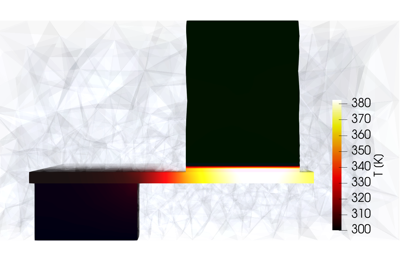
Fig. 1: Temperature of a 2T-SOT-MRAM device at switching. The device is shown in a cut through the symmetry plane. During the switching, high current densities pass through the device, and its temperature rises, altering the magnetic properties of the magnetic materials.
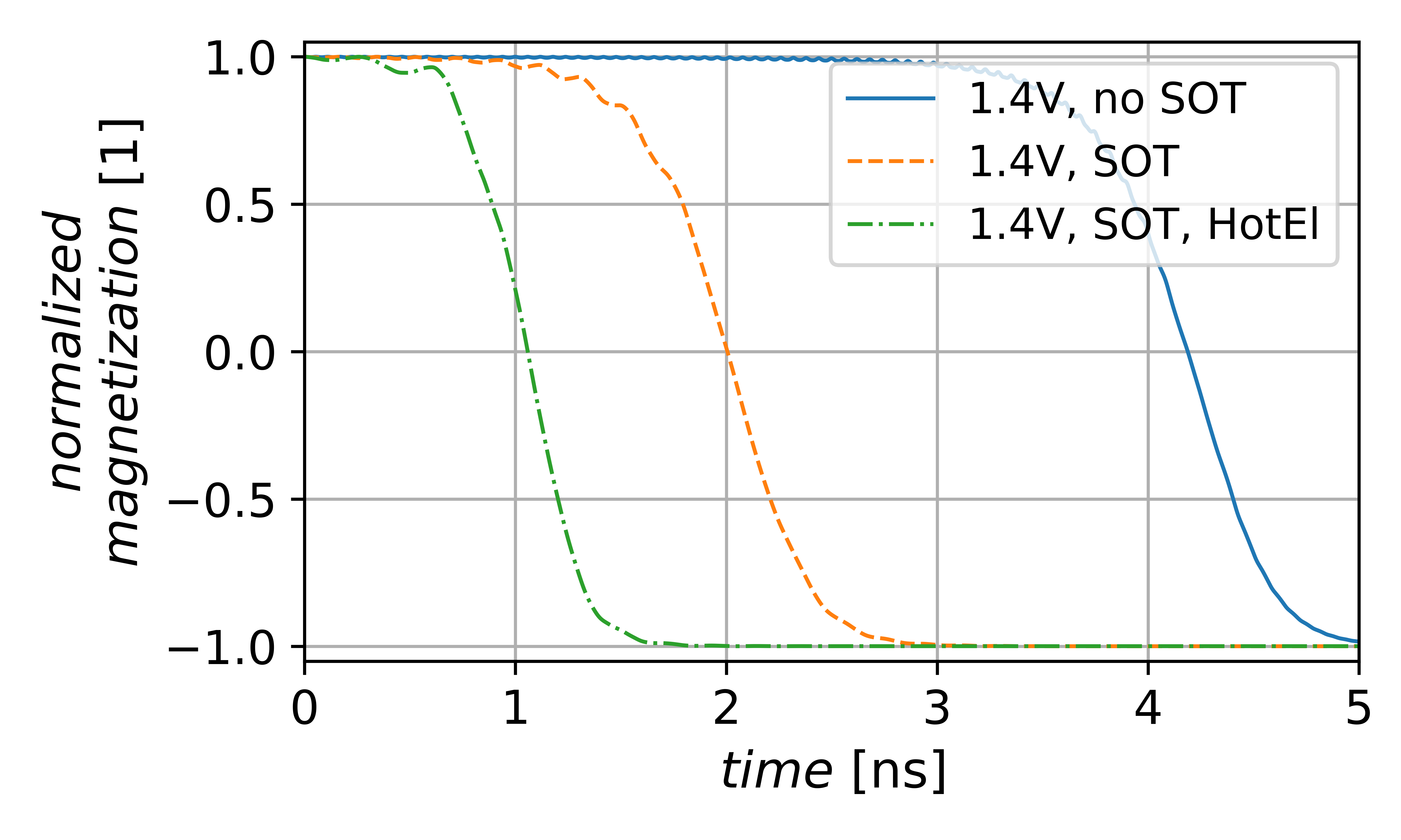
Fig. 2: Free-layer magnetization reversal of the 2T-SOT-MRAM. When an additional SOT is considered (dashed orange), the incubation time is significantly reduced. Introducing asymmetric heating (dash-dotted green) increases the FL temperature and further reduces the incubation time.
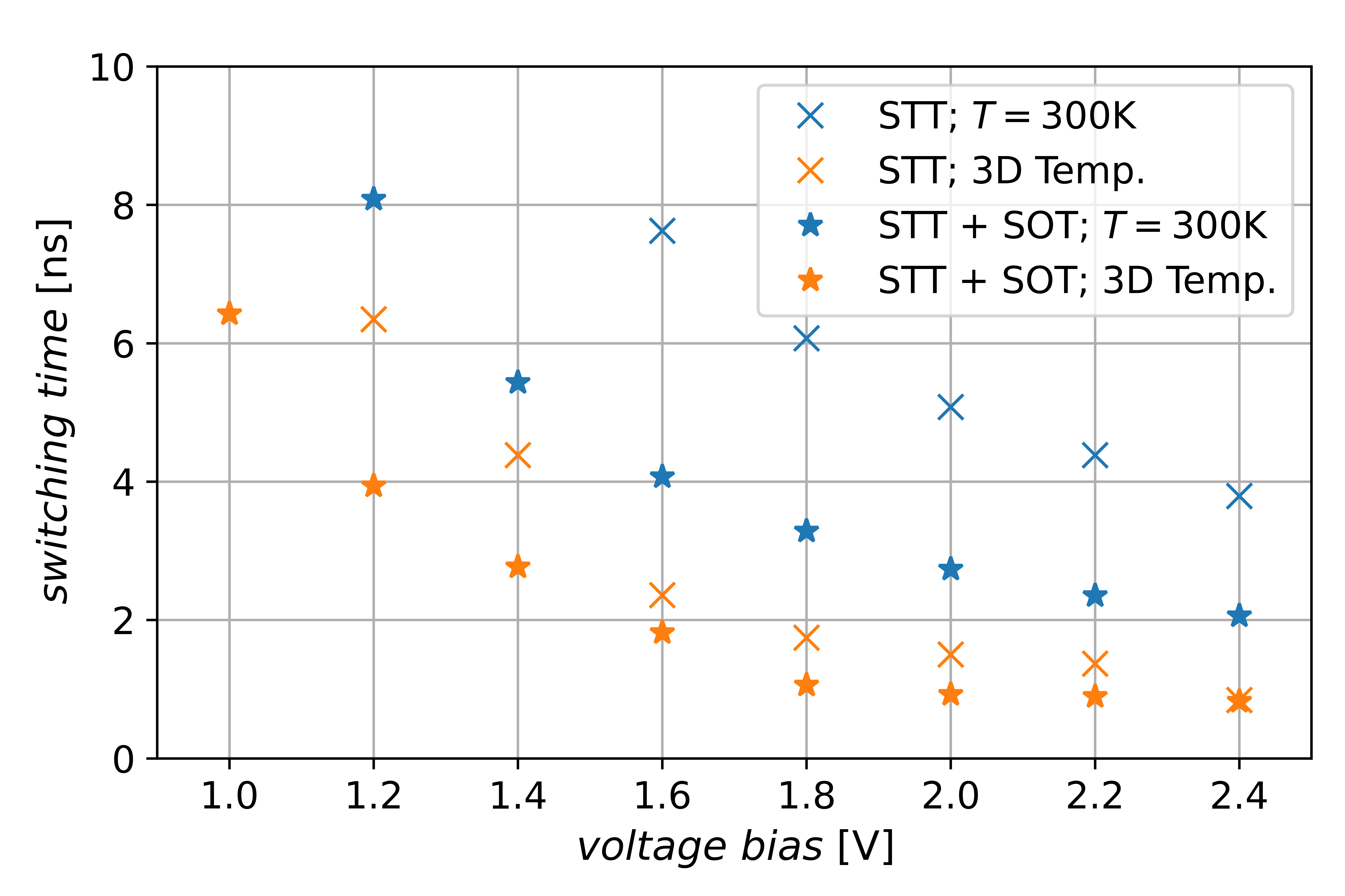
Fig. 3: Switching time dependence on the applied bias voltage. The difference between the conventional 2T-STT-MRAM (crosses) and 2T-SOT-MRAM (stars) is shown. A significant reduction in switching times is observed with the presence of the additional SOT. Introducing the fully three-dimensional (3D) temperature model (orange) further reduces the incubation times.