
 |
|
||||
BiographyMario Bendra was born in 1993 in Steyr, Austria. He received his BSc degree in Mechanical Engineering from the University of Applied Sciences Upper Austria in 2017. After an exchange semester at the University of the Sunshine Coast, Australia in 2018, he received the degree of Diplomingenieur in Mechanical Engineering from the University of Applied Sciences Upper Austria in 2019. Mario joined the Institute for Microelectronics in October 2020, where he is working towards his doctoral degree focusing on developing and implementing advanced computational approaches to simulate and optimize spin-transfer torque magnetoresistive memories. |
|||||
Influence of Interface Exchange Coupling in Multilayered Spintronic Structures
Spin-transfer torque magnetoresistive random access memory (STT-MRAM) represents a breakthrough in nonvolatile memory, leveraging magnetic tunnel junctions (MTJs) with CoFeB/MgO structures for enhanced density and miniaturization. However, the reduced cell size raises reliability concerns, notably back-hopping, which jeopardizes memory stability. Interlayer exchange coupling (IEC) has emerged as a pivotal factor for improving cell performance and stability, particularly in complex configurations like multi-level cells (MLCs).
IEC, influencing magnetic alignment through non-magnetic spacers, varies with spacer thickness, which is crucial for tailoring MTJ performance for various applications. Advances in MTJ technology aim to improve interfacial anisotropy, leading to the commercialization of sub-10 nm MTJs.
Our study introduces a detailed modeling approach, focusing on IEC in STT-MRAM cells, illustrated in Fig. 1. The MRAM cell structure features a multilayered MTJ, detailed in the ultra-scaled MRAM cell depiction in Fig. 1, with a diameter of 2.3 nm.
The Landau-Lifshitz-Gilbert (LLG) equation, used to model normalized magnetization dynamics, incorporates the finite element method (FEM) for analysis, represented as:
∂m/∂t = -γm×Heff + αm×(∂m/∂t) + (1/MS)TS
IEC's influence is explained by theories such as Rudermann-Kittel-Kasuya-Yosida (RKKY), highlighting its dependence on spacer material and thickness. The free energy density due to IEC is described by:
E = -J1cos(Δφ) - J2cos2(Δφ)
Fig. 2 illustrates the trilayer structure, focusing on the interaction through the non-magnetic spacer or tunnel barrier, with magnetization vectors in adjacent layers depicted at the interfaces.
Switching simulations, as shown in Fig. 3, explore the effects of varying IEC constants on the switching dynamics, revealing the critical role of IEC in device operation. These simulations, particularly the magnetization trajectories during P to AP transitions, underscore the significant impact of IEC on switching dynamics, which is essential for optimizing spintronic device performance.
In summary, this study challenges prevailing assumptions about magnetic coupling in multilayered structures, offering insights into leveraging IEC for enhanced performance in spintronic devices and magnetic storage technology.

Fig. 1: This figure shows the intricate design of a multilayered MRAM cell in a more comprehensible form. Color-coding is utilized to differentiate components: the RL is marked in violet, the FL is in green, and the TB or NMS is in orange. Non-magnetic (NM) contacts are represented in gray. White zigzag lines highlight interfacial engineering regions. The interaction strengths between the RL and the first FL (FL1) and between FL1 and the second FL (FL2) are denoted by Jiec1 and Jiec1, respectively.
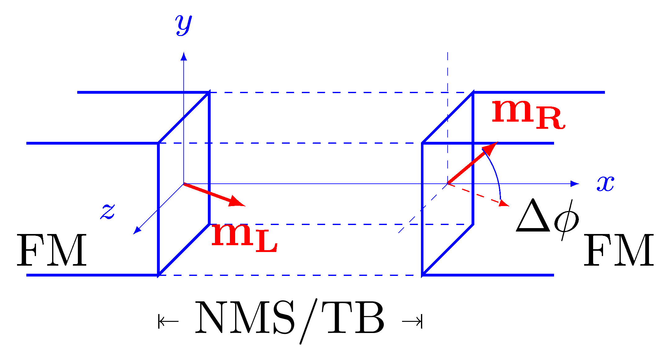
Fig. 2: Schematic depiction of a trilayer structure composed of left and right semi-infinite ferromagnetic (FM) regions divided by a TB or an NMS layer. The interface magnetization on the left FM interface points in an arbitrary direction, whereas the interface magnetization within the right FM forms an angle ∆φ relative to the magnetization of the left FM.
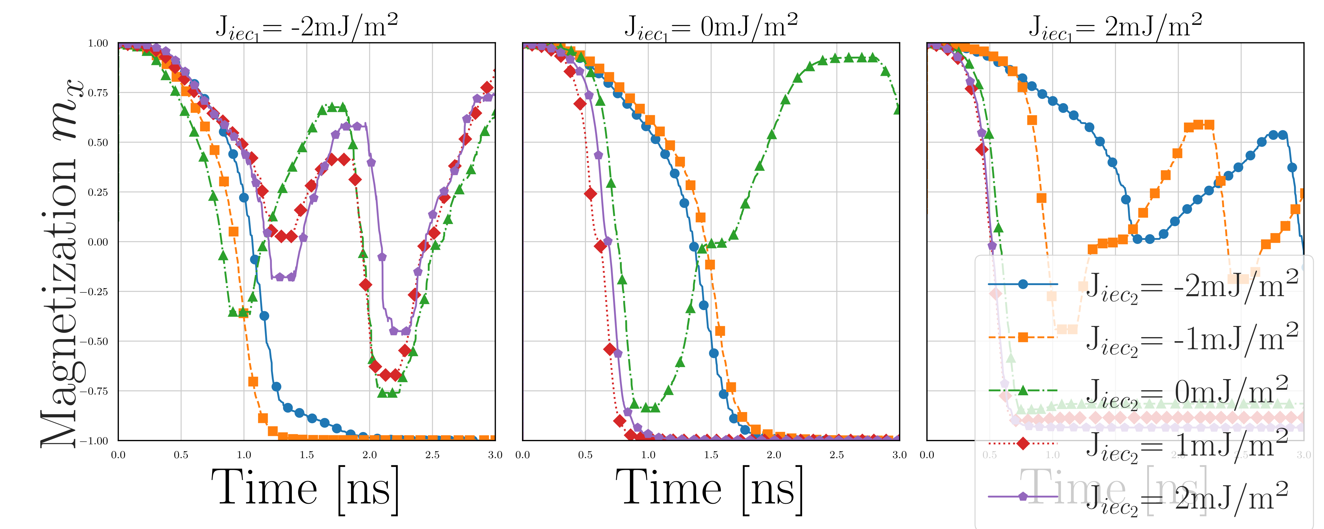
Fig. 3: Magnetization dynamics during P to AP switching in multilayer MRAM configurations, highlighting the critical role of IEC
parameters, Jiec1 and Jiec2 . This figure mirrors experimental observations on magnetic coupling effects. Jiec1 is set to a negative value in the left panel, showcasing its impact on the reversal process. The middle panel provides a comparative analysis with Jiec1 at zero, and the right panel explores the dynamics under a positive Jiec1. These scenarios underscore the nuanced influence of IEC on the complex switching mechanisms in next-gen MRAM technologies.