 |
|
Biography
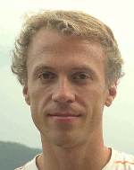
Paul Manstetten was born 1984 in Berlin, Germany. He studied Mechatronics at the University of Applied Sciences Regensburg (Dipl.-Ing.) and Computational Engineering at the University of Erlangen-Nuremberg (MSc.). After three years as an application engineer for optical simulations at OSRAM Opto Semiconductors in Regensburg he joined the Institute for Microelectronics in September 2015 as a project assistant. He is researching high performance numerical approaches for Technology CAD within the scope of the Christian Doppler Laboratory for High Performance TCAD.
Using One-Dimensional Radiosity to Model Neutral Flux in Convex High Aspect Ratio Structures
In the context of negative-AND flash cell fabrication, the processing of high aspect ratio (HAR) holes is a key prerequisite. One way in which to fabricate such HAR structures is ion-enhanced plasma etching. The simulation of such plasma etching processes requires the recalculation of the local neutral flux distribution on the surface at each simulation time step. This is necessary because the surface evolves at every simulation time step. For HAR structures, the local flux originating from re-emission is dominant, and the local flux rates can easily vary by orders of magnitude along the structure depth. At the spatial resolutions desired for practical simulations, this leads to very high computational costs for a full, conventional three-dimensional computation of the local neutral flux using Monte Carlo ray tracing or radiosity-based methods. We therefore suggest using a one-dimensional approximation for the calculation of the local neutral flux inside HAR structures.
We have recently introduced a one-dimensional radiosity framework for the calculation of the neutral flux in convex-shaped, rotationally symmetric holes and convex-shaped trenches of infinite length. The framework is intended to replace the full three-dimensional simulation step required to calculate the neutral flux during plasma etching simulations. The radiosity approach naturally treats all sources and re-emissions as ideally diffuse, a common assumption for neutral particles. The wall of the structures is modeled with a constant sticking probability. The bottom is modeled as a fully adsorbing area with a sticking probability. The opening area of the structure models the source and is also fully adsorbing. The radiosity equation has been formulated from a "receiving" perspective that allows for fully adsorbing elements.
The treatment of trenches and holes only differs in the view factor computation. We have established a general formula for the view factor between the inner surfaces of two coaxial cone-like segments. For the trenches, the crossed-strings method is used to compute the view factor between any two segments of a trench. The computed adsorbed flux is normalized to the flux that a surface of the same sticking probability would adsorb if fully planar-exposed to the source. Several geometric variations, including an extended, tapered, and kinked sidewall, visualized in Fig. 1, are applied to a hole and a trench of aspect ratio (AR = depth/width) 25. Fig. 2 compares the resulting flux distributions along the wall and at the bottom for wall sticking probabilities 0.2 and 0.01. To summarize, low sticking probabilities increase the influence of geometric variations on the flux distributions along the wall and especially at the bottom of HAR structures.

Fig. 1: Cross sections of the geometric variations of the wall for holes and trenches (shown for AR = 3). Starting from a vertical wall, the bottom width is increased by 25% and reduced by 25%. Finally, the width at 1/2 of the total depth is increased by 12.5% to form a kink.

Fig. 2: Normalized flux distributions along the wall and at the bottom of a hole and a trench with AR = 25 for wall sticking probabilities 0.2 (a) and (b) and 0.01 (c) and (d). The geometry of the structures are varied (according to Fig. 1) starting from a perfect cylinder and a perfect vertical trench, respectively. Lines represent the results of the reference ray tracing simulator.


