


Next: 4.3.5 Mesh Refinement at
Up: 4.3 Simulation in FEDOS
Previous: 4.3.3 Assembly of the
4.3.4 Calculation of the Mechanical Stress
The discretization of the mechanical problem presented in Section 4.2.4 yields the linear system of equations
 |
(4.96) |
with
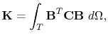 |
(4.97) |
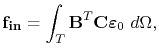 |
(4.98) |
Since
 ,
,
 , and
, and
 are constant within an element, the assembly of (4.96) is performed in FEDOS using
 |
(4.99) |
and
 |
(4.100) |
The mechanical problem has to be solved each time step after the solution of the vacancy dynamics problem, as shown in Figure 4.3.
Thus, for the time step  , the internal force vector is determined by the electromigration induced strain given in (3.82), so that
 |
(4.101) |
From (3.78), the trace of the electromigration strain for each node of the tetrahedron is calculated by
 |
(4.102) |
resulting in the element strain which is set in (4.101),
 |
(4.103) |
The solution of (4.96) yields the interconnect line deformation due to electromigration.
Once the displacement field
 is determined, the electromigration induced stress vector for an element is obtained using (4.60),
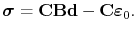 |
(4.104) |
The mechanical stress at each node is obtained by an extrapolation from the stress calculated for the elements, given by (4.104). The stress at a particular node is calculated by performing a weighted average of the stress on all elements connected to the node. Considering a node
 and defining the set of all elements which contain the node as
  , the mechanical stress at the node
  is given by
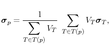 |
(4.105) |
where  is the volume, and
 is the stress calculated by (4.104) for the element
  .
.
Next: 4.3.5 Mesh Refinement at
Up: 4.3 Simulation in FEDOS
Previous: 4.3.3 Assembly of the
R. L. de Orio: Electromigration Modeling and Simulation