

Next: E.3 Rectangular Aperture
Up: E. Diffraction in Far
Previous: E.1 Linear Approximation
E.2 Circular Aperture
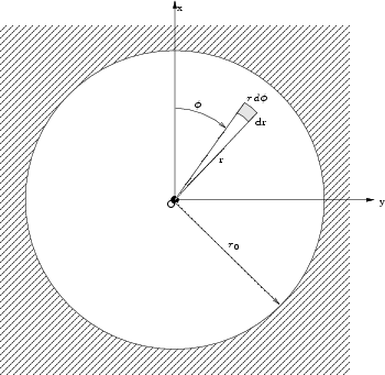
Figure E.4 shows the aperture plane with
the coordinates  and
and
 .
.
Figure E.4:
Coordinate system in a circular aperture
 |
The transmission function of the aperture is
 |
(E.30) |
and
 |
|
 |
(E.31) |
Using polar coordinates for the transformed coordinates  and
and  defined in the
previous section
 |
|
 |
(E.32) |
gives
 |
(E.33) |
We are now reviewing the case with the source being on the optical axis of the
aperture ( ) which yields
 |
(E.34) |
where
 |
(E.35) |
is the radial distance of the projection point from the z-axis in the
projection plane.  is the angle of the projection point seen from
the aperture (refer to Figure E.2).
The FOURIER transform of
 can be calculated from
(E.27). The differential area element
 is in polar coordinates
as depicted by Figure E.4
The exponential factor in the integral of (E.27)
in the above defined coordinate system gives
Therefore (E.27) is in polar coordinates
![$\displaystyle T(\rho,\phi') \cong \int\limits_0^{\tilde{r_0}} \tilde{r} \int\li...
...i} \exp[-i 2 \pi \tilde{r} \cos(\tilde{\phi}-\phi')] d\tilde{\phi} d\tilde{r}$](img571.png) |
(E.36) |
The inner integrand of this solution is the well known BESSEL function of zeroth order and is
defined as
![$\displaystyle J_0(w) = \frac{1}{2\pi}\int\limits_0^{2\pi} \exp[-iw\cos(\tilde{\phi}-\phi')] d\tilde{\phi}$](img572.png) |
(E.37) |
by using this definition with (E.27) the
FOURIER transform of a circular aperture gives
 |
(E.38) |
which is independent of  as a consequence of the rotational symmetry of
the aperture. Applying a coordinate transformation
 to
the integral of (E.38) yields
 |
(E.39) |
To solve this integral one can use a relation between BESSEL functions of
different order
 |
(E.40) |
integrating (E.40) with  gives
gives
Using this result in (E.39) gives
finally
 |
(E.42) |
or
 |
(E.43) |
In the center of the diffraction pattern with  the properties of the
BESSEL function give
yielding
 |
(E.44) |
Taking (E.29) the electrical field of the
diffraction pattern behind a circular aperture is finally
 |
(E.45) |
The average optical intensity is proportional to the square of the absolute
electrical field. Therefore the intensity for diffraction behind a circular
aperture is
 |
(E.46) |
with
 |
(E.47) |
By using the (E.14) and
(E.35) in (E.46) one
obtains
 |
(E.48) |
Substituting  from (E.47) into above
equation yields
 |
(E.49) |
With the substitution
 |
(E.50) |
(which is dimensionless) the intensity is finally
![$\displaystyle I'(\rho) = I'(0) \left(\frac{2J_1(x)}{x}\right)^2\left(1-x^2\left[\frac{\lambda}{2\pi\tilde{r_0}}\right]^2\right)$](img593.png) |
(E.51) |
The (for most cases valid) assumption that the aperture radius is much bigger than
the wavelength (
 ) the intensity is
 |
(E.52) |
Which is the well known intensity distribution for a circular aperture given
in many textbooks.
The variable  reduces to
 |
(E.53) |
for the assumption mentioned above.
Figure E.5:
AIRY-disk with rings
|
|


Next: E.3 Rectangular Aperture
Up: E. Diffraction in Far
Previous: E.1 Linear Approximation
R. Minixhofer: Integrating Technology Simulation
into the Semiconductor Manufacturing Environment


![$\displaystyle J_0(w) = \frac{1}{2\pi}\int\limits_0^{2\pi} \exp[-iw\cos(\tilde{\phi}-\phi')] d\tilde{\phi}$](img572.png)


