

Next: 2.10 Summary
Up: 2 Theory of Single
Previous: 2.8 Single Electron Transistor
In Section 2.4.2, the
tunnel rate was derived from first order perturbation
theory. However, in the Coulomb blockade regime, where the first order tunnel rate is
very low, or at zero temperature even zero, higher order processes may
become important. In the case of the double tunnel junction, a second
order process is also possible for bias voltages below the Coulomb blockade, because
the change in free energy for a process with tunneling in both junctions is
negative even though the energy differences for independent tunneling at
either junction are positive. Since one elementary charge is transported over
the whole bias voltage drop, for a second order tunnel event in field
direction, the change in free energy is -eVb. In multiple tunnel
junction circuits higher order co-tunneling is possible. Generally a circuit consisting
of N junctions will show co-tunneling up to the Nth order. Second order co-tunneling looks like a
simultaneous tunneling of two electrons through two junctions, which suggests
the term co-tunneling. From another point of view this process is a quantum tunneling
through a barrier built by two junctions and the island. Since the island
may be quite large the resulting structure of tunnel junction - island -
tunnel junction, compared to a single junction, is
macroscopic, and hence the process is also called
macroscopic quantum
tunneling of charge (q-MQT).
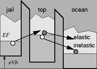
Fig. 2.15 shows the energy diagram of the
inelastic and
elastic co-tunneling.
Figure 2.15:
Energy diagram for co-tunneling. Two distinct forms of co-tunneling, elastic and
inelastic co-tunneling, are observable.
 |
Electrons are allowed to tunnel via an
intermediate virtual
state where first order tunneling would be suppressed. Suppose an electron
cannot tunnel directly from jail to ocean. Also tunneling from jail to top
is impossible because of missing energy. Nevertheless, an electron will escape
to ocean via an intermediate virtual state, where two simultaneous tunnel
events have an overall negative change in free energy. One could picture this
process in the following simplified way. An electron starting at jail
overcomes the energy difference to top, violating the energy conservation for
a very short time allowed by Heisenberg's uncertainty principle. If a
different electron from top tunnels
in the same very short time to ocean, then overall an electron escaped from
jail to ocean. This process is called inelastic co-tunneling, because it produces an
electron-hole excitation in the island which is eventually dissipated through
carrier-carrier interactions. A second process, the elastic co-tunneling corresponds
to the same electron tunneling into and out of a virtual state. An electron
tunnels through either one junction, travels through the island, and
finally tunnels out of the island through the other junction. The phase of
the electron is preserved which makes elastic co-tunneling a coherent process. Elastic co-tunneling strongly depends on the internal
structure of the
island. Usually inelastic co-tunneling is dominant in comparison to
elastic co-tunneling except at very small bias voltages and temperatures or very
low energy state densities in the quantum dot
[10] [11].
Inelastic co-tunneling in small normal-metal tunnel junctions, as opposed to
superconducting tunnel junctions, was first experimentally
observed by L. Geerligs et al. [40], in a silicon quantum dot
by H. Matsuoka and S. Kimura [84], and elastic co-tunneling by
A. Hanna et al. [50]. Co-tunneling is a major source of errors in SET devices.
Especially in SET logic devices that rely on the presence or absence of a
single or few number of electrons, co-tunneling is an important issue to consider.
Using Fermi's golden rule
(Appendix E) [30],
the second order co-tunneling rate may be written
as [11]

where
 is the difference in free energy for tunneling through
the xth barrier. The two terms,
 and
and
 ,
represent
the fact, that the process
could start either with a tunneling in junction one or two. Summing over
all possible initial and final states, the total
tunnel rate for the general
case of Nth-order co-tunneling is given by [10] [12]
[43]

where the  are the intermediate energy levels electrons tunnel
to and from, and
 denotes all permutations of the
numbers
 .
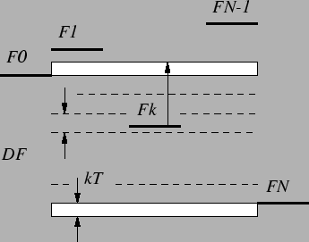
An Nth-order co-tunneling event starts at energy level F0 and passes through
levels
 ,
as shown in Fig. 2.16.
 denotes the difference to the
initial level,
 .
The quantum mechanical amplitudes
of all co-tunneling sequences with the same initial and final states are added
coherently to give the total rate (2.44). For different sequences
with the same initial and final level, the intermediate levels Fx need
not be necessarily the same. It is not possible
to solve (2.44) in the general case. Second order co-tunneling at
zero temperature is one of the special cases where an analytic solution
exists (see Appendix F).
![\begin{gather}\Gamma^{(2)}\arrowvert_{T=0}=\frac{\hbar V_b}{2\pi e^3R_{T1}R_{T2}...
...ln
\left\vert 1+\frac{eV_b}{\Delta F_i}\right\vert\right)-2\right]
\end{gather}](img180.gif)
An approximation introduced by H. Jensen and J. Martinis [56]
for (2.44) is to assume that the free energy difference
 is, on the average, equally divided over the electron-hole
excitation energies. Thus,
 ,
and
(2.46) becomes

The co-tunneling rate may then be analytically calculated as

The result of the perturbative calculation (2.44)
diverges if
there are states with energies Fk in the window
 .
A consequence of this is the divergence of (2.49) for
 .
L. Fonseca et al. [32] suggested to
move all
levels Fk that fall in this window a distance kBT over the nearest
border in order to avoid all divergences. Another possibility to regularize
the singularities is to take the finite lifetime of
island states into
account [69] or to partially re-sum the infinite perturbation
expansion [72]. A theory for
inelastic co-tunneling through a quantum
dot in the regime of strong tunneling, where one or both contacts are close
to perfect transmission was developed in [36].
Figure 2.16:
Energy levels of an Nth-order co-tunneling event. The dashed lines
give the points where the tunnel rate approximation (2.49)
diverges. To circumvent the singularities, energy levels falling in the
range [F0,FN] are moved to the closer border. The buffer zones kBT
have to be added to prevent a second divergence in the case of F0=FN.
 |


Next: 2.10 Summary
Up: 2 Theory of Single
Previous: 2.8 Single Electron Transistor
Christoph Wasshuber


![]() is the difference in free energy for tunneling through
the xth barrier. The two terms,
is the difference in free energy for tunneling through
the xth barrier. The two terms,
![]() and
and
![]() ,
represent
the fact, that the process
could start either with a tunneling in junction one or two. Summing over
all possible initial and final states, the total
tunnel rate for the general
case of Nth-order co-tunneling is given by [10] [12]
[43]
,
represent
the fact, that the process
could start either with a tunneling in junction one or two. Summing over
all possible initial and final states, the total
tunnel rate for the general
case of Nth-order co-tunneling is given by [10] [12]
[43]

![]() are the intermediate energy levels electrons tunnel
to and from, and
are the intermediate energy levels electrons tunnel
to and from, and
![]() denotes all permutations of the
numbers
denotes all permutations of the
numbers
![]() .
An Nth-order co-tunneling event starts at energy level F0 and passes through
levels
.
An Nth-order co-tunneling event starts at energy level F0 and passes through
levels
![]() ,
as shown in Fig. 2.16.
,
as shown in Fig. 2.16.
![]() denotes the difference to the
initial level,
denotes the difference to the
initial level,
![]() .
The quantum mechanical amplitudes
of all co-tunneling sequences with the same initial and final states are added
coherently to give the total rate (2.44). For different sequences
with the same initial and final level, the intermediate levels Fx need
not be necessarily the same. It is not possible
to solve (2.44) in the general case. Second order co-tunneling at
zero temperature is one of the special cases where an analytic solution
exists (see Appendix F).
.
The quantum mechanical amplitudes
of all co-tunneling sequences with the same initial and final states are added
coherently to give the total rate (2.44). For different sequences
with the same initial and final level, the intermediate levels Fx need
not be necessarily the same. It is not possible
to solve (2.44) in the general case. Second order co-tunneling at
zero temperature is one of the special cases where an analytic solution
exists (see Appendix F).
![\begin{gather}\Gamma^{(2)}\arrowvert_{T=0}=\frac{\hbar V_b}{2\pi e^3R_{T1}R_{T2}...
...ln
\left\vert 1+\frac{eV_b}{\Delta F_i}\right\vert\right)-2\right]
\end{gather}](img180.gif)
![]() is, on the average, equally divided over the electron-hole
excitation energies. Thus,
is, on the average, equally divided over the electron-hole
excitation energies. Thus,
![]() ,
and
(2.46) becomes
,
and
(2.46) becomes
![]()

![]() .
A consequence of this is the divergence of (2.49) for
.
A consequence of this is the divergence of (2.49) for
![]() .
L. Fonseca et al. [32] suggested to
move all
levels Fk that fall in this window a distance kBT over the nearest
border in order to avoid all divergences. Another possibility to regularize
the singularities is to take the finite lifetime of
island states into
account [69] or to partially re-sum the infinite perturbation
expansion [72]. A theory for
inelastic co-tunneling through a quantum
dot in the regime of strong tunneling, where one or both contacts are close
to perfect transmission was developed in [36].
.
L. Fonseca et al. [32] suggested to
move all
levels Fk that fall in this window a distance kBT over the nearest
border in order to avoid all divergences. Another possibility to regularize
the singularities is to take the finite lifetime of
island states into
account [69] or to partially re-sum the infinite perturbation
expansion [72]. A theory for
inelastic co-tunneling through a quantum
dot in the regime of strong tunneling, where one or both contacts are close
to perfect transmission was developed in [36].
